The idea is to run the Scalextric Challenger car on a digital track to have a decent opponent.
The only way of achieving this is to put a SSD Chip in the car, so here we go!
First look at the inside of the car…
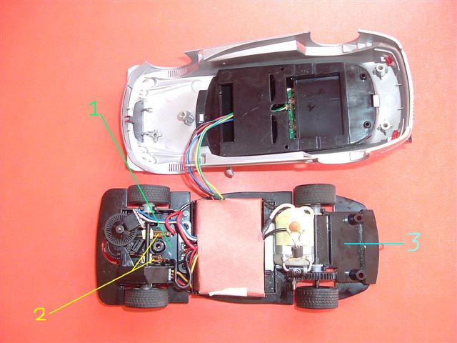
The ir LED will need to be as near the guide as possible – the only real space to put it is 1 in the pic.
The chip itself can only really fit at the back of the car 3.
The power currently comes in via the connectors 2.
A quick look at the chip shows that it is not suited for this install (yet)…

The ir LED is far too close to the chip 1 and will have to be extended.
The power in wires 2 are also far too short and will have to be extended, and probably have the connectors from the car attached.
The motor wires 3 are, however long enough to connect to the wires that would usually serve the inner workings of the car (connected to 2 in the first pic).
I have tried to keep the chip as intact as possible so if I ever need to remove / sell the chip or the car I can put it back with the minimum of fuss, however as soon as I started to look at soldering onto the pick-ups they fell off and I ended up removing them!
The chip in the process of being stripped:

And the finished chip:

Now it is just a question of mounting it.
The hole was drilled, then the LED put in place, unfortunately this meant a bit of a struggle with the board the LED is attached to (you could remove the LED from the board and solder wires directly to it but I prefer to use the board to help mount the LED).


As you can see from the second picture the board is at an angle but the LED is pointing downwards (trust me).
With the rest of the wires connected it is time to fix the board in position. There is only 1 quick easy and effective way to do this that I have found… Hot Glue Gun!

Notice also the red tape around the wires at the back of the car above the engine – this was necessary to keep the LED wires away from the cogs next to them. The white tape is covering joins in the cable (I have twisted the wires together and then ‘tinned’ with solder to keep together). Notice how many wires go over the top of the red box – this is unavoidable with the chip placement at the rear.
The chip is a tight fit with the body on – the next picture shows the car with the rear axle removed so that you can see the chip in place. There are 2 lugs at the top of the spae that you have to push the chip bechind, but as you can see it is a snug fit!

And finally the car assembled.

The only issue here is the fact that the undertray is pushed down by the new wires travelling along the top of the casing. Hopefully this will not affect performance, may even improve it with a bit of 'ground effect'!
You can just about see the bulge of the LED behind the front wheels.
This has been tested OK back on analogue but seeing as my powerbases blew on a different chipping project (fills you with confidence, eh?) I am waiting for replacements before testing on digital!!
Have fun.
Aaron